RESEARCH
Magnetic Design and Loss Analysis for High Frequency High Power DC/DC Transformer

Nanocrystalline is the best candidate for the SST design in terms of core loss and saturation flux density for frequency around 50 kHz. A transformers core loss is determined by a working flux waveform, which is excited by input voltage. Our proposed CLLC resonant converter is a frequency controlled converter with a square input voltage waveform. A Rectangular Extension Steinmetz Equation (RESE) is employed to exactly predict core loss under rectangular voltage excitation. Calculation results are verified by actually measuring core loss density at different working temperatures, frequencies, and different flux density amplitude.
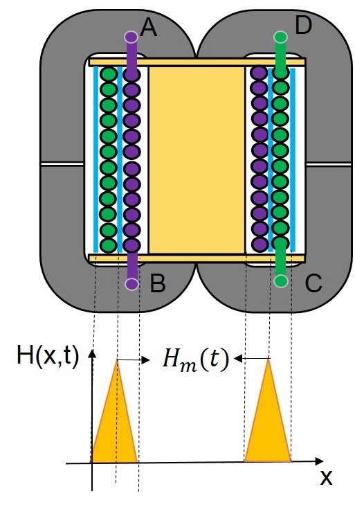
A litz wire is used in the SST transformer since it contains separately insulated wire strands twisted or braided together, enabling low-resistance high-current conductors at frequencies up to hundreds of kHz. Based on valid assumptions, the litz wire winding loss model should only consider both eddy current flowing inside each strand due to an external field and a conduction loss neglecting the eddy current effect. The former can be analytically calculated basing on the field distribution characteristic shown in Fig.1. The latter is easy to calculated via a dc resistance of conductor. This winding loss model is also verified by a sample transformer with a similar structure.
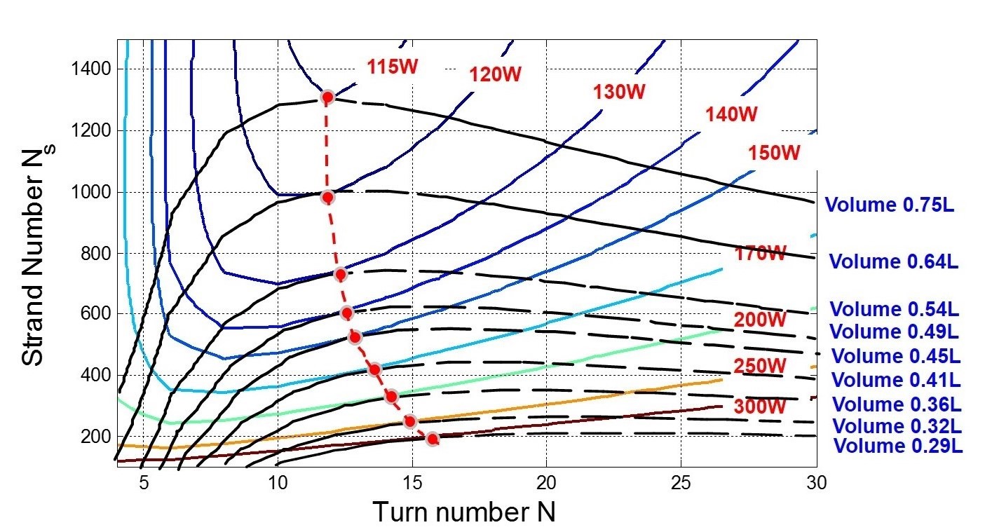
In order to simplify analysis, the first step determines the strand diameter as an AWG 38 strand. Wide range turn number N and strand number Ns are swept to calculate the transform-ers total loss and total volume. For each specific volume among different combination of N and Ns, a minimum loss point (red point) can always be found. The connection line of these points should contribute to the optimal design curve for different volume values. Design trade-offs be-tween total loss and volume is explained basing on loss calculation and volume evaluation. The strand diameter and core loss density impact on transformer design are all investigated. Finally, a completed SST design result is proposed with the necessary design parameters.


