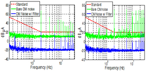
Fig. 1. 2 MHz noise spectrum.
There is hope that Gallium-nitride (GaN) power electronics technology can lead to significant increases in the switching frequency of power converters. The ability to switch more frequently gives the potential to increase the power density of converters. EMI filters engage a large portion of system weight and volume, and it is not so straight forward to conclude that increasing switching frequency will benefit the size and weight reduction of EMI filters. In this work, the impact of increasing switching frequency on the single stage EMI filter size and weight is investigated in a DC/DC converter for low voltage bus aircraft applications. In the initial paper design, it was assumed that the corner frequency of the EMI filter is determined by the low frequency noise spike. Obtained in that way, the differential mode (DM) filter size and weight would reduce increasing switching frequency, while the Common Mode (CM) filter show very little increase due to a smaller CM propagation path impedance at higher frequencies. For verification purposes, two different resonant LLC converters are implemented at switching frequencies of 1 MHz and 2 MHz.
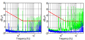
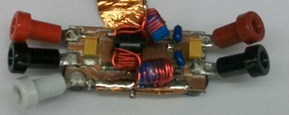
Experiment results show that the EMI filter was larger and heavier for the 2 MHz case (Fig. 4) due to high frequency noise spikes at tens of mega-hertz (Figs. 1-2). This conclusion was made based on the low frequency attenuation requirement. However, in the hardware implementation the real limitation comes from the spectrum at high frequencies, 20 MHz - 30 MHz. The problems at high frequencies arise from several different factors. First, the permeability of the nanocrystaline material drops significantly with the frequency, thus making this material less effective in the 20 MHz - 30 MHz range. Secondly, parasitics of the filter components, such as the ESL of the capacitors and EPC of the inductors, degrade the performance of the filter. The conclusions of this paper are limited to the assumptions and approaches taken, such as single stage passive filtering, magnetics materials choice, no integration (Fig 3) and the design procedure.

Fig. 2. 1 MHz noise spectrum: left - DM Noise; right - CM noise.

Fig. 3. 1 MHz EMI filter.

Fig. 4. Converter magnetics volume and weight for 1 MHz and 2 MHz.


